The impact of Optimised Cathodic Protection
Corrosion Instruments are in the midst of a research project which aims to determine the impact of Optimised Cathodic Protection (OCP) on the working life of various assets.
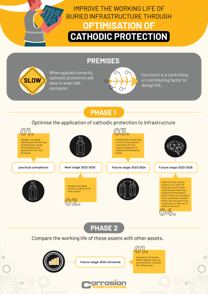
Phase 1 of the study is to enable OCP, whilst Phase 2 is to investigate the impact of OCP.


Empirical data, collected through assessment of corrosion rates before and after OCP and between similar assets with and without OCP would be invaluable to this study. We will be calling upon our customers to explore the potential use of non-sensitive data over the coming years.
Clearly, this argument implies a couple of premises!

Skipping the maths lesson, we believe that CP affects the corrosion rate and that the corrosion rate affects the working life of some assets.
But what is optimised CP?
OCP can be neatly quantified and described in a small, controlled lab environment. But what about in a large, distributed operational environment? What does OCP of a 1000km long pipeline look like?
Let’s describe a model structure (an imaginary pipeline) so that we can clearly consider the factors which could contribute to less than optimal CP.
Our model pipeline is 1000km long, has an Impressed Current Cathodic Protection (ICCP) unit every 50km and a test point every 2km resulting in roughly 20 CP sites and 500 test points. The pipeline is entirely buried. To inspect any small portion of it is possible, but time-consuming and costly.
Let us first note that corrosion can occur at any point along the structure and that the structure passes through continually changing environments and that the environment at any specified location can change on a continual basis over time.
Let’s also note that CP can be practically monitored only at a relatively small number of discrete locations (the test points) and CP is only applied at a smaller number of discrete locations (ICCP Sites).
It might already be clear that practical, real-life OCP is starting to look different to OCP on a metal sample in a lab that can be:
- Wholly observed,
- is located in a single, homogenous, controlled environment,
- and can have CP applied almost uniformly to the entirety of the sample.
In practice, numerous factors impact CP efficacy, though only a few of these are practically controllable. Thus, these are what will ultimately define the efficacy.
For the sake of keeping this study practical and not entirely academic, we will define practical OCP as:
Cathodic protection, applied to real infrastructure, which is optimised through all practically controllable factors.
The goals are:
- Meet the protection criteria at the maximum number of test points possible, given the number, capacity and arrangement of TR’s and sacrificial anodes, and
- Maintain Goal 1 on a time continual basis for the maximum amount of time.
These goals must be achieved whilst ensuring that polarisation limits are not exceeded at any test points.
These goals naturally implicate several operational requirements.
For example, we clearly need to monitor the polarisation at as many locations as possible in order to know if we have achieved Goal 1.
Furthermore, the structure passes through various environments (soil types, PH, moisture levels etc) which each vary continuously over time. So goal 2 implies a minimum sampling rate for polarisation monitoring that should be in line with changing seasons, changing climates, changing environments and aging assets.
CP outages and failures must be rectified as soon as possible to achieve Goal 2. If possible CP outages and failures should be avoided altogether through proactive management (preventative maintenance). A high enough polarisation sample rate may enable the pre-empting of such failures, outages or deficiencies. In fact, machine learning applied to a high sample rate of a comprehensive dataset may allow for the early identification (or possibly pre-empting) of pipeline events such as:
- Sudden changes to the coating condition (e.g. disbondment).
- Sudden changes to the structure’s environment (e.g. flooding).
- Third-party interference (e.g. dig-ups, impacts, new CP/traction/transmission systems).
Continual monitoring and timely response to outages are not enough to maintain OCP on a dynamic, ever-changing, widely distributed system. To ensure the protection has maximum coverage for the maximum time, the CP system needs to be able to respond continually. A system that can automatically respond on a daily basis to the dynamics of the infrastructure, its environment and its applied CP, is a critical requirement of OCP. Furthermore, any changes to the applied CP should account for the polarisation of the entire asset, not just a single sample point adjacent to the TR.
So what does practical OCP look like?
- Continually sampling the entire alignment of the asset and automatically adjusting the applied CP to ensure the protection criteria is met for as much of the asset as possible at any given time.
- Immediate notification of CP failures or deficiencies, coupled with timely rectification.
- Where possible, the pre-emptive indication of future CP failures or deficiencies with timely preventative maintenance.
PHASE 1 – STAGE 1
Corrosion Instruments are already part way through Phase 1 of this project! The first hurdle was to build the system that was capable of monitoring both the applied CP and the resulting polarisation at test points.
This monitoring equipment had to tick a few boxes in order to be truly useful:
- Enable continual and compliant monitoring of Polarisation (instant off potentials)
- Automate the various types of CP Surveys
- Work in a wide range of applications and locations
- Be installed easily
- Facilitate the use of long-life stable reference cell technology
- Require minimal maintenance or operational intervention
- Be cost-effective

PHASE 1 – REMAINING STAGES
The hardware developed in Phase 1 has been designed to enable the remaining stages to be remotely implemented over time.
Early adopters have already started installing hardware as either a commercial project to reduce the operation and maintenance costs of their CP systems or in partnership with Corrosion Instruments to lead the journey towards OCP.
Where applicable, the control component of our TRULinks (TRU Monitoring and control hardware) will be gradually enabled. the second stage of Phase 1 is controlability starting with basic remote control. operators will be able to remotely adjust the setpoint of their TRU’s from CI-Tx Central, our cloud-based CP management portal.
Phase 2 is a lot more academic than Phase 1, involving the long-term study of the result of OCP. We aim to quantify the actual benefit in terms of both the longevity of the asset, and the reduction in operational and maintenance costs. Starting in 2024 we will be inviting asset owners and operators to partner with us for this study.

Stage 3 is automatic closed-loop control. In this stage, we will gradually enable CI-Tx Central to automatically adjust TRU setpoints in response to data gathered from test point installed polarisation monitoring equipment. This is the first time such dynamic control of a CP system has been possible thanks to our proprietary CI-Tx system (patent pending).
This final stage will be a deep dive into the data, where we aim to see what we can learn from this unprecedented dataset. We hope to make industry-changing findings regarding:
- CP cause and effect (predictors and indicators)
- Sequence of Events models
- Telluric impact on CP and Structures
- Dynamics and interference between multiple adjacent CP systems
- The impact of long-term environmental changes on CP systems
Thank you for your interest in this project! If you wish to collaborate with Corrosion Instruments by way of data and knowledge sharing, please contact us. If you would like to apply continual monitoring and/or automated control to your CP systems, please contact us.
For your interest, we have provided a very high-level description of some of the system components below:
Corrosion Instrument’s CI-Tx system aims to ensure the application of OCP.

Polilog and Interlog continually monitor the asset’s polarisation. By measuring true Instant-Off potentials at least once per day, they can each automatically complete surveys such as Depolarisation, Stray Current and Instant-Off surveys. These are the only test point monitors we know of that can enable the stable use of permanent copper reference cells (which require minimum isolation to the structure of 100MOhms).
Interlog adds a small relay enabling it to interrupt sacrificial anodes or coupons.


TRULink monitors the application of CP, enables the measurement of instant-off potentials (through our proprietary Infrequent Interrupt Routine), and enables automatic closed-loop control of the applied CP.

CI-Tx Central allows for immediate notification of CP issues, under protection, outages etc.
Soon, we will start to apply closed-loop control and then machine learning to the dataset to see what sort of predictive analysis or event indicators we can identify.

We will be officially launching our CI-Tx system within the next few weeks. If you would like to receive official marketing material, please subscribe or contact us.